


Description
PALLET ASSEMBLY TABLE
adjustable for various sizes
PT-1900
IDENTIFICATION
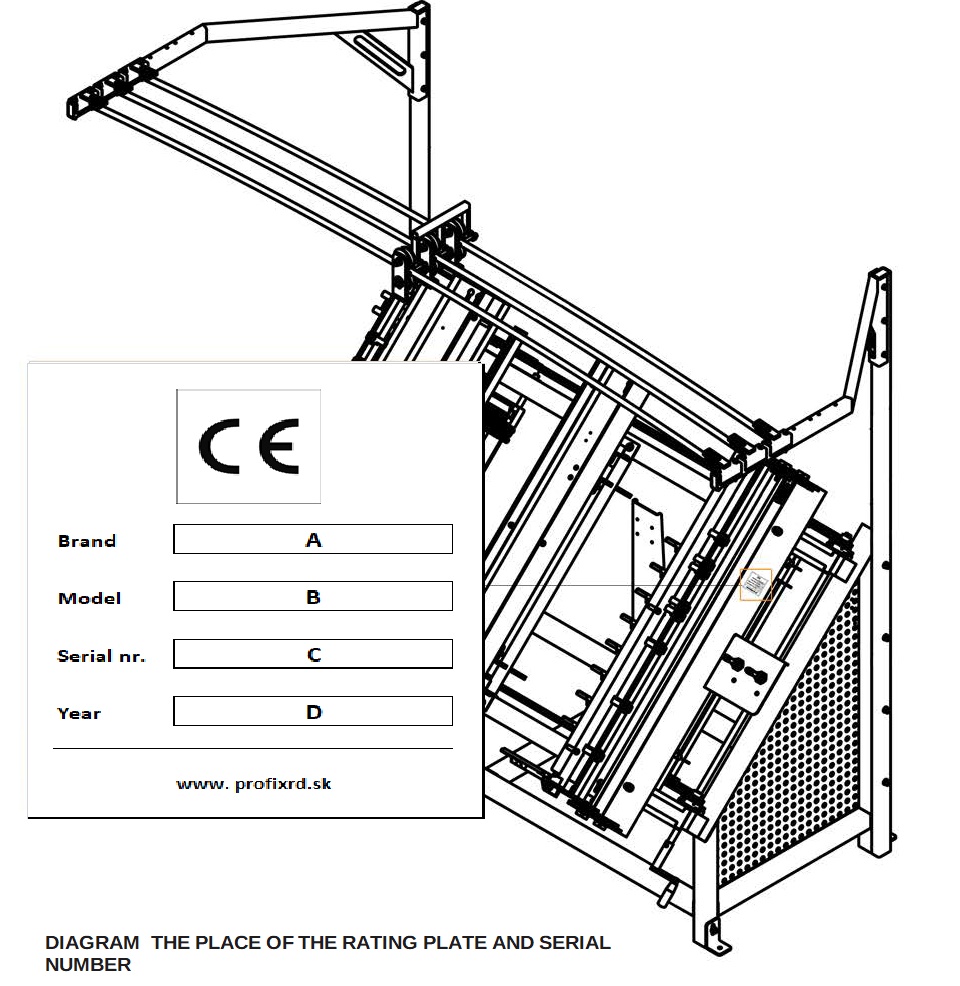
Pallet assembly table PT-1900 was marked with a rating plate which is affixed on the right side of the table, on the side support, in its upper part, above the control panel with levers. When the product is bought, it is necessary to check the serial number of the table with the number in guarantee card, sales note and manual. The meaning of particular numbers from the rating plate is written below:
A – the brand of the machine
B – the model of the machine
C- eight-digit serial number
D – year of construction
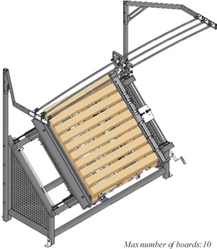
INTENDED USE
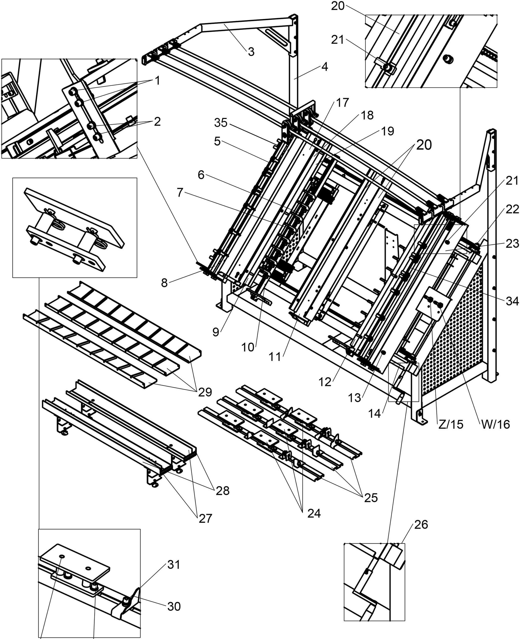
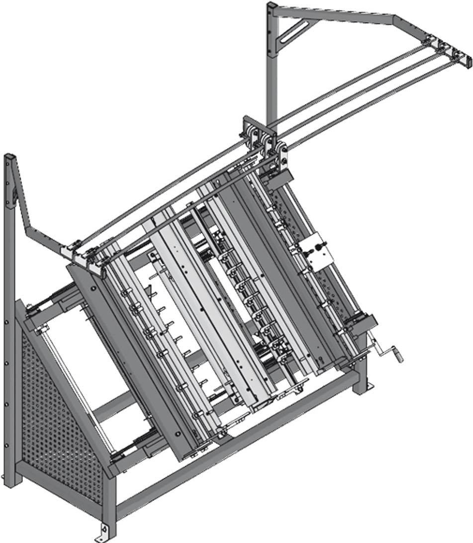
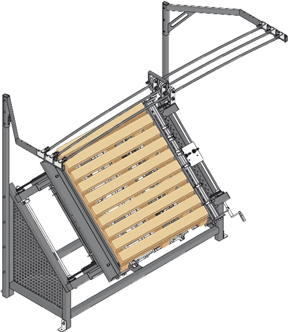
PT-1900 is a universal nailing machine for wooden pallets of different types. There is a rail mounting system for balancers in its upper part which is equipped with movable carts (trolleys) where nailers are suspended. PT-1900 ensures the work study and comfort. lt guarantees the increase of work efficiency, space- saving (it takes only 3,3 m2 ) and reduces the costs of preparing templates for different types of pallets.
During traditional nailing two workers are able to produce about 250 pallets during one shift. Over the same period of time, a single operator using PT-1900 has the capability to produce about 210-230 pallets.
PT-1900:
- ensures increase of work productivity
- it acts like a template for EUR pallets and different sizes also those on 2, 3 or 4 rows of blocks
- designed to be manned by one operator
- enables quick and easy modification from one size into another
- it is equipped with function of pneumatic clamping of blocks and the pushback of the ready pallet
it ensures the work study by the system of suspended nailers on balancers
| EQUIPMENT | PT-1900 | NUMBER |
| MANUAL | ST | 1 pe. |
| GUARANTEE CARD | ST | 1 pe. |
| NOTIFICATION OF FAILURE FORM/ INCIDENT REPORT | ST | 1 pe. |
| TABLE – THE MAIN BODY | ST | 1 pe. |
| VERTICAL PROFILE | ST | 2 pes. |
| HORIZONTAL PROFILE | ST | 2 pes. |
| TWO-PIECE CRANE | ST | 3 pes. |
| MOVABLE CART (TROLLEY) WITH A SNAP HOOK | ST | 3 pes. |
| NAILER POWER SUPPLY TIPPED
WITH A FEMALE QUICK COUPLING |
ST | 3 pes. |
| TEMPLATE FOR THE BOTTOM OF THE PALLET | ST | 3 pes. |
| CRANK | ST | 1 pe. |
| FILTER-REGULATOR | ST | 1 pe. |
| AIR PREPARATION BLOCK I FLR AIR UNI T | ST | 2 pes. |
| BALANCER | OP | 2 pes. |
| NAILER | OP | 2 pes. |
| COMB 200 mm WIDE | OP | on client’s request |
TRANSPORT, ASSEMBLY, ACTUATION
PT-1900 table is ready for sale in a part-assembled condition. ltems delivered with the table include technical manual, guarantee card, standard equipment mentioned in “ITEMS OF EQUIPMENT” section and accessory options (available on customer’s order). The delivery takes place by means of the car transport according to individual agreements with the customer. During loading and unloading operations general rules of proceedings and safety regulations for such conditions should be observed. lt is required for people operating trans-shipping equipment to be entitled to man their machines. PT-1900 must be fastened firmly on the platform with transport belts, protected against displacement. During trans-shipment special attention should be paid not to damage or scratch the elements of table equipment or the coat paint. Lifting the cargo must be carried out only by the qualified personnel. ONLY A FORKLIFT OF ADEQUATE SIZE AND WITH FORKS WHICH ARE LONG ENOUGH SHALL BE USED FOR OPERATIONS!!!
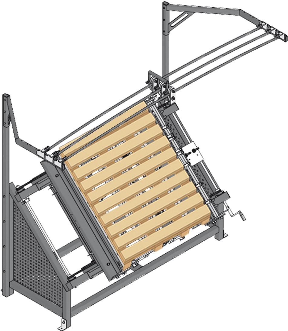
CONSTRUCTION AND PEFORMANCE OF THE TABLE
PT-1900 is a machine designed for pallet producers who appreciate high quality, speed, diversity of pallet types, easiness to modify to adifferent size and possibility to be manned by one operator. Thanks to many pneumatic elements, taking advantage of only compressed air PT-1900 guarantees comfortable, fast and effective work. What is more, by adjustment possibilities pallets may have different sizes as well as different number of deckboards and blocks. “CLAMPING” gives the possibility to place the deckboards and blocks precisely before nailing. There is no possibility for the elements to change the position, so the final product is very accurate. lt is possible to make any pallet you wish, of any size in the perimeter of the table.
PREPARATION FOR WORK BEFORE ACTUATION
The producer guarantees that the table is fully operational, was quality-controlled according to thorough procedures and permitted for use. However, it does not exempt the operator from checking the machine before work. Technical manual is provided along with the table.Prior to work actuation the operator is obliged to inspect the technical condition of the table. What is mare, by regulation, adjust the table to required position.
To this end:
- get familiar with the manual and follow its instructions
- carry out the inspection of the table concerning its condition (dents, cracks, breaks, breaks off)
lf there are no objections, compressed air can be connected to the machine. lt shall be done with a femałe Quick coupling, a hose of inner diameter at least 12 mm. The capacity of the compressor shall be at least 300 I/min.Next, using central air regulator set the operating pressure not more than 3 – 4 bar. Carry out tests of clamping and ejecting. The control over clamping and ejecting takes place by changing the position of “CLAMP” and “EJECT” levers.
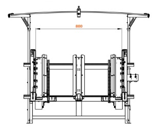
TABLE SIZE ADJUSTMENT
For below mentioned activities 6 and 10 mm Allen wrench should be used (delivered with the table). Due to different sizes of pallets that may be produced, the table requires to be modified. In order to change the table to a required size, below mentioned activities must be undertaken:
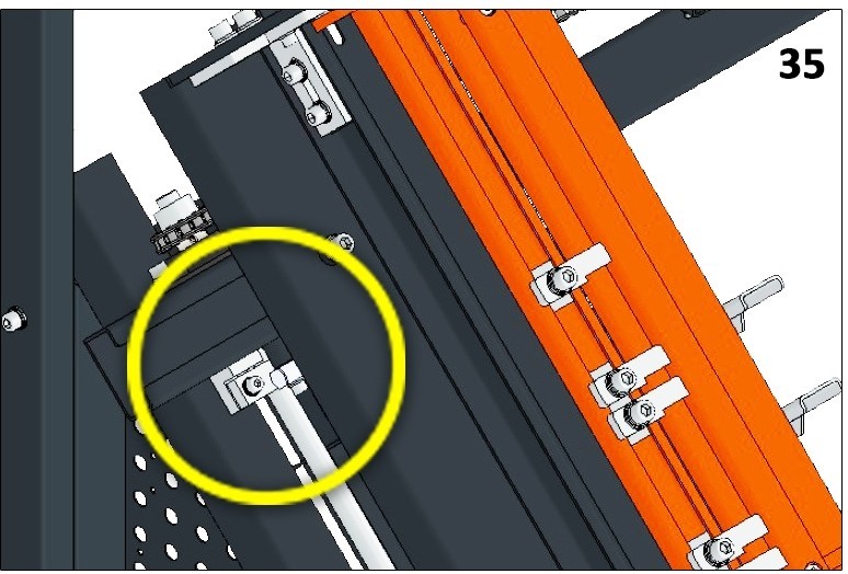
- STEP 1 Release the brake {35) situated in the left upper part of the table.
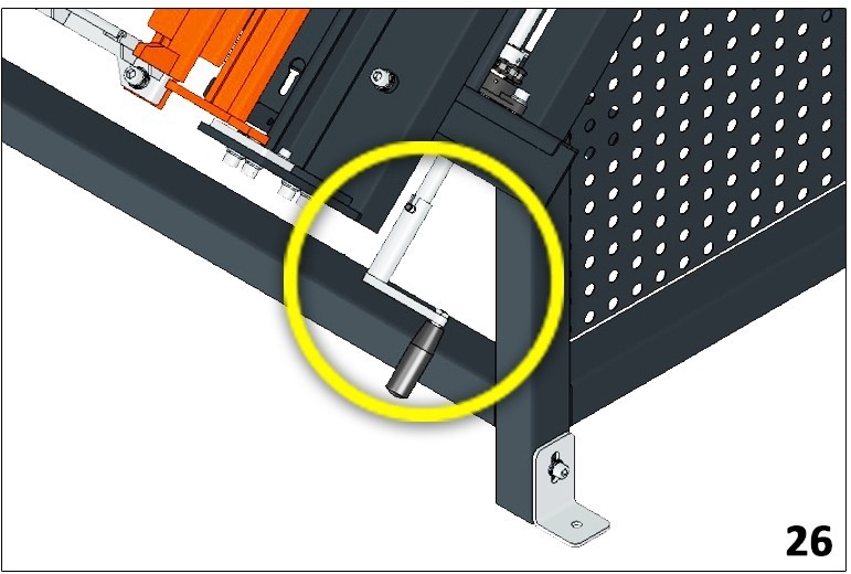
- STEP 2 Using the crank (26) set the accurate width of the pallet
- STEP 3 Block the brake {35) by tightening the socket
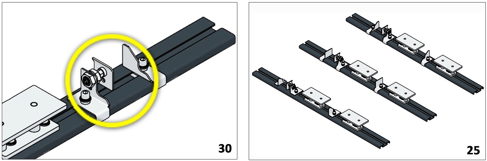
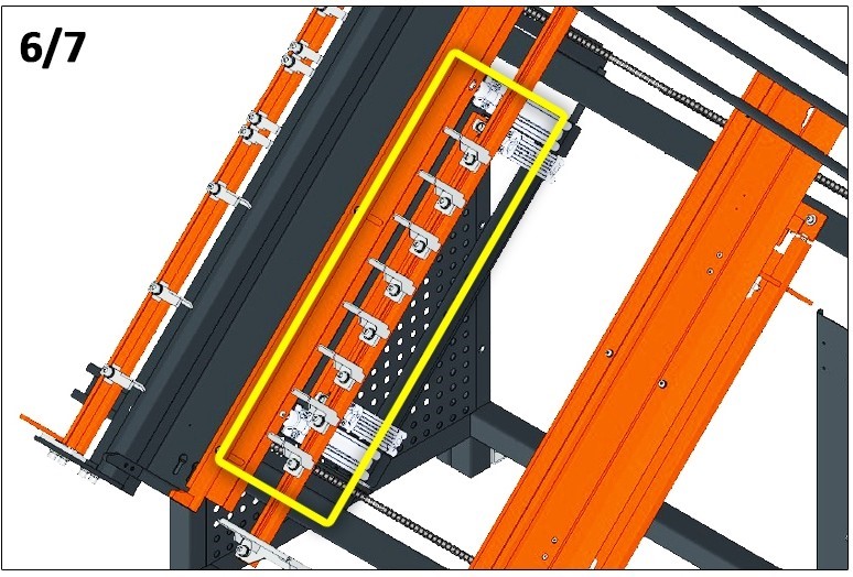
- STEP 4 Regulate the pallet blocks by loosening the angles {30) which are located on the battens {25). Set the required position of the blocks and tighten them firmly to the battens.
- STEP 5 Clamp the blocks using “Z” lever (Z/15). Put the top
- STEP 6 Depending on the number of top deckboards regulate the combs (7) which are tightened to the battens (6).
Combs which are not going to be used for a particular type of the pallet move away or remove from the battens.
- STEP 7 Nail the top of the
- STEP 8 Release the clamp using “Z” lever {Z/15).
- STEP 9 Eject the pallet using “W” lever {W/16).
- STEP 10 Rotate the pallet 180 degrees (tum over) and then release “W” lever {W/16).
- STEP 11 Make sure the pallet clings to the
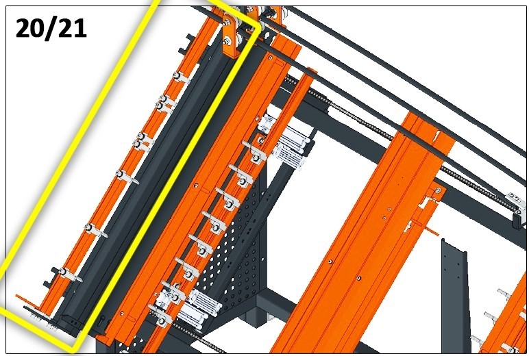
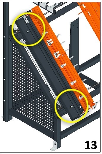
- STEP 12 Take the T-tracks {21) down, next regulate every comb cantilever which is located in the side T-track {20).
Move away the elements which are not going to be used.
-
STEP 13 Put the bottom deckboards on the comb cantilevers and nail
In case of nailing stringer pallets, push the battens with combs and side battens (after loosening two screws {13) together with side support to the required distance.
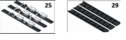
Remove the battens with angles {25) in order to put them in place of cantilevers. The basic toolkit comprises also of templates {29) to nail semi-finished EUR type pallets*.The templates must replace the battens with angles {25). Thanks to that, it is possible to make 9 semi-finished pallets.
TERM OF USE
lf certain parts are needed, please submit your request at info@profixrd.sk.com
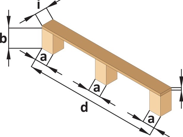
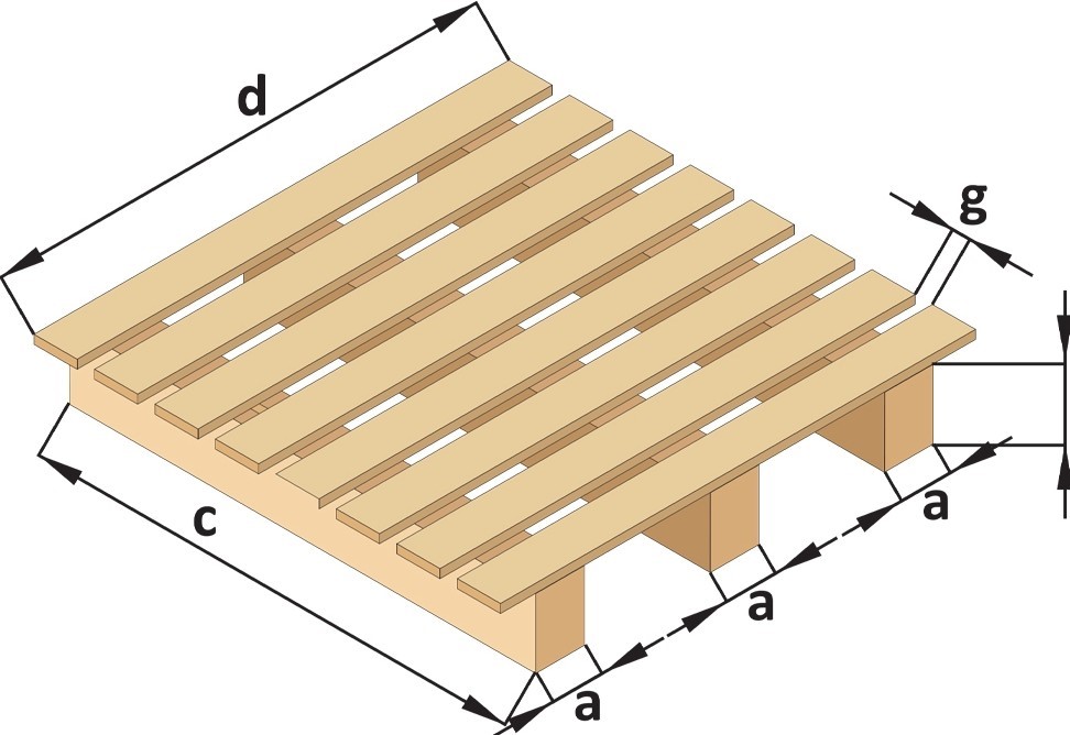
ASSEMBLY OF SEMI-FINISHED PRODUCTS (bottom deckboards with 2 or 3 blocks)
Dimensions of nailed elements:

a. 70 -145 mm
b. 70 -120 mm
d. 800 -1900 mm
e. 12 - 27 mm
i.  70 -145 mm
The set consists of:
- 2 templates with scale to set the external blocks (29} placed on external supports (17} regulated symmetrically in relation to the centre, by means of the chain drive
- 1 template with scale to set the middle blocks (29} situated on a stationary middle support (11}
- 2 T-tracks with combs to set the boards (34}
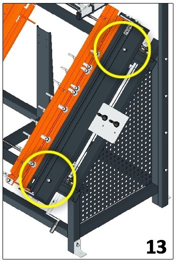
2 pneumatic lifts (12} for the pushback of the ready pallets
The sequence of operations:
- Put the blocks on templates (29}
- Unblock Z lever- CLAMP
- Take the T-tracks with combs down (34}
- Set the boards
- Nail the elements
- Unblock Z lever – clamping (Z/15}
Force the elements out by changing W lever- EJECT (W/16}
The number of horizontal bords depends on the board width (8-13}.
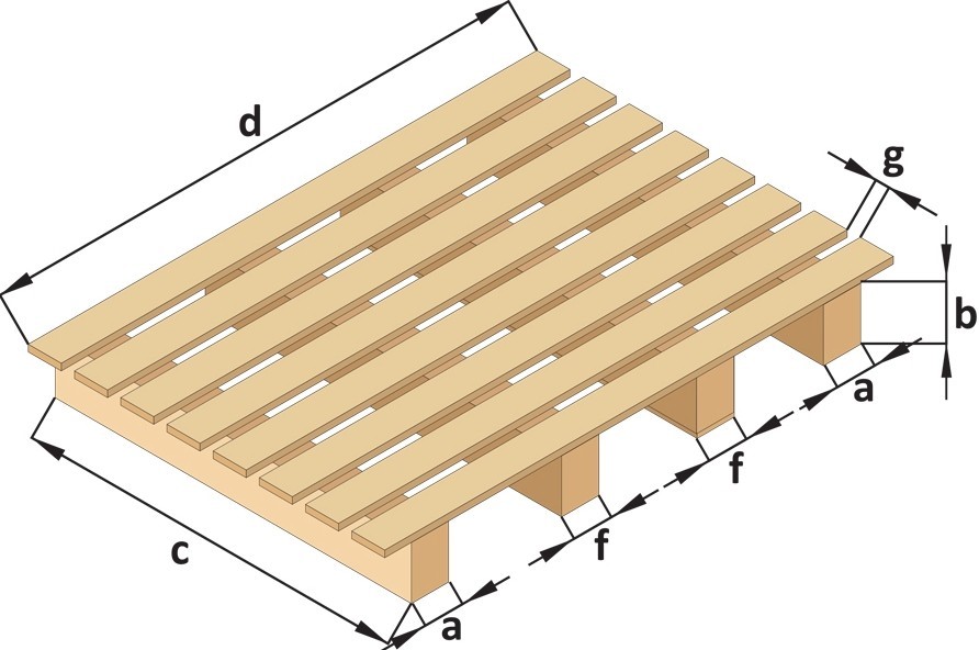
ASSEMBLY OF EUR-TYPE PALLETS
Dimensions of nailed elements:
a, 65 -145 mm
b. 70-110mm
c. max. 1300 mm
d. 900 – 1900 mm*
e. 12 – 27 mm
g. min.16 mm
h. 65-145 mm
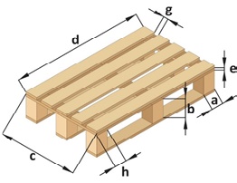
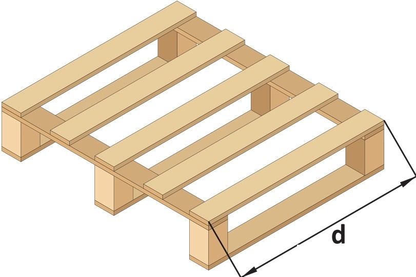
*Fora double row pallet, size d, minimum 600 mm
The set consists of:
- 2 templates with scale to set the external blocks (29} placed on external supports (17} regulated symmetrically in relation to the centre, by means of the chain drive
- 1 template with scale to set the middle blocks (29} situated on a stationary middle support (11}
- 2 T-tracks with combs (5) to set the bottom boards after nailing the top and overturning
- 2 internaI combs (10} to set the top boards
- 2 pneumatic lifts (12} for the pushback of the ready pallet.
ASSEMBLY OF EUR-TYPE PALLETS
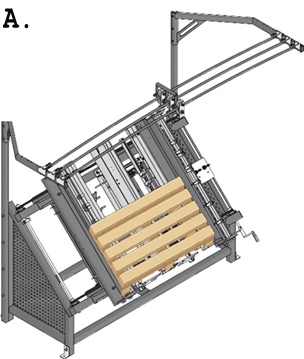
EUR-type tour-way pallets
Nailing is undertaken by a two-step process:
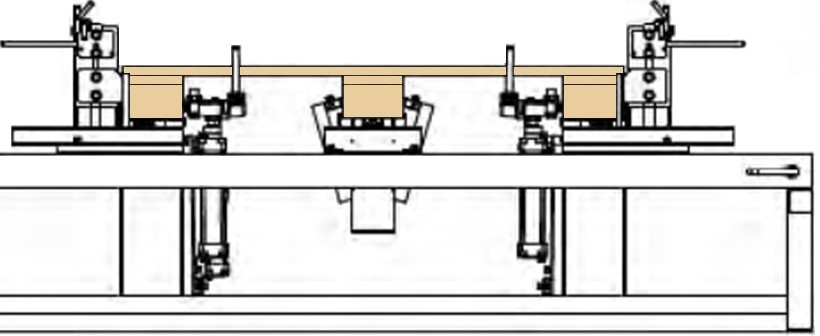
A. Nailing top boards to the blocks – pneumatic clamping of the blocks, next after nailing, pneumatic lifting to overturn the pallet
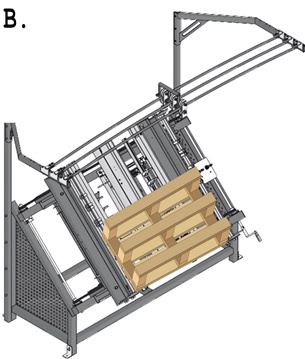
B. Nailing the bottom boards
The sequence of operations:
A.
- Set the blocks regulating the position of the angle irons (30}
- change the position of Z lever – CLAMP (Z/15}
- set the top boards using the position of the combs (10}
- nail the elements
- unblock Z lever- CLAMP (Z/15}
- force the elements out by changing W lever- EJECT (W/16}
- rotate the pallet 180 degrees (overturn
B.
- unblock lever W – EJ ECT (W/16}
- take the T-tracks with combs down (34
- set the bottom boards
- nail the elements
- lift the ready pallet changing W lever- EJECT (W/16}
ASSEMBLY OF STRINGER PALLETS (on 3 stringers)
Dimensions of nailed elements:- a. 40 -145 mm
- b. 75 -140 mm
- c. 600 – 1300 mm
- d. 800 – 1900 mm
- f. 40 -125 mm
- g. min.16 mm
The set consists of:
- 2 external support s (17} regulate d symmetrically in relation to the centre , by means of the chain drive sys
- 1 stationary middle support (11}
- 2 T-trac s with combs to set the boards (34}
- 2 pneumatic lift s (12} for the pushback of the ready pall et
The sequence of operations:
- Set the stringers on supports (17} (11} (remove the battens with angles from the support s)
- Change Z lever – CLAM P (Z/15}
- Take the T-tracks with combs down (5)
- Set the boards
- Nail the element s
- Unblock Z lever – CLAM P (Z/15}
- Force the element s out by changing W lever – EJ ECT (W/16}
ASSEMBLY OF STRINGER PALLETS (on 4 stringers)

Dimensions of nailed elements:
a. 40 -145 mm
b. 75 -140 mm
c. 600 - 1300 mm
d. 800 - 1900 mm
f.  40 -125 mm
g. min.16mm
The number of horizontal bords depends on the board width (8-13}.
The set consists of:
- 2 external supports (13} regulated symmetrically in relation to the centre, by means of the chain drive system
- 1 set for middle stringers (27} (additional equipment)
- 2 T-tracks with combs to set the boards (34}
- 2 pneumatic lifts (12} for the pushback of the ready pallet
The sequence of operations:
- Set the stringers both on supports (17} and the set for middle stringers (27}
- Change Z lever- CLAMP (Z/15}
- Take the T-tracks with combs down (34}
- Set the boards
- Nail the elements
- Unblock Z lever – CLAMP (Z/15}
- Force the elements out by changing W lever- EJECT (W/16}
MAINTENANCE AND REGULATION
In order to guarantee the proper work of the pneumatic table, it is required to follow the below mentioned procedures:
- examine the chain tension (in the bottom and upper side of the table), chain lubrication (grease)
- examine the table size accuracy, its symmetry and In case of any irregularities it is required to regulate the nominal values of the table by loosening (with due care) the regulating elements and taking full measurements of the table.
- refill the oil of pneumatic tools which is located in two FLR Air Units on the right and left side of the table
- monitor the pressure parameters both in exchanged FLR Air Units and the power supply central regulator
- exchange filters in FLR Air Units and the central regulator every 6 months
- monitor the tightening of the screws
- monitor if there are no leakiness in pneumatic installation
- check periodically the condition of vertical profiles, raiIs and trolleys
GUARANTEE CARD
Na me of the machine/ Na me of item
Type of the machine
Serial number
Recipient/ Customer
Sell-by date
Terms of guarantee:
- PROFIX RD, s.r.o. shall guarantee that the machine is fully operational in accordance with technical and operative conditions included in the
- The guarantee will be respected after submission of correctly filled guarantee card and original invoice of the The dates from guarantee card and invoice must be the same.
- The guarantee period is 12
- Repairs shall be carried out free of Repairs shall not exceed 14 days, as far as it is not necessary to bring spare parts from the manufacturer. The guarantee period extends by the time of the repair.
- Guarantee claims will be rejected in case of damages resulting from the fault of the Purchaser or from improper operation (contrary to the instructions in the user manual) as well as those contrary to the provisions of the existing Directive on electromechanical
- The Seller shall not be liable for inappropriate choice of the
- Excluded from the guarantee are mechanical damages of the construction, switchers etc. caused by the
- Outside the scope of the guarantee are technical parameters of the machine except standards declared by the
- Outside the scope of the guarantee are all wearing parts and all materials used for maintenance g. inserts in FLR Air Units.
- Guarantee claims will be rejected in case of damages resulting from the fault of the Purchaser during improper
- The guarantee becomes void in case of:
- faiIure to respect the deadlines, lack of documentation concerning purchase and showing filters and oil
- inadequate air compressed pressure
- faiIure to comply with the provisions concerning shift and weekly reviews as well as maintenance (see point 5)
- misuse of the machine contrary to the user manual
- PROFIX RD liability under guarantee relates to repairs, exchange or return of the overpaid amount whereby the choice is made by PROFIX RD. Any other claims are excluded from the scope of the
- The ownership of the faulty parts belongs to PROFIX RD.
- The guarantee applies to manufacturing defects, faulty construction and defected/improper materials used for their
- PROFIX RD liability under guarantee is void in case of repairs and maintenance provided by third Outside the scope of the guarantee are any modifications provided by third parties or the Purchaser himself.
- Packing of ordered goods is being monitored and recorded data is one of the methods used for analysing quantity
- Seller’s liability under warranty shall be precluded.
